Skip to main content
Home
Products
Swing Gate Openers
Shop Accessories
Shop Spare Parts
Slide Gate Openers
Shop Accessories
Shop Gate Hardware
Shop Spare Parts
Driveway Gates
Articles
Shop
My Account
Support
Contact
Home
Products
Swing Gate Openers
Shop Accessories
Shop Spare Parts
Slide Gate Openers
Shop Accessories
Shop Gate Hardware
Shop Spare Parts
Driveway Gates
Articles
Shop
My Account
Support
Contact
Select the system below for wiring in BMGi's Electric Gate Lock
Gate Lock Installation
View Here
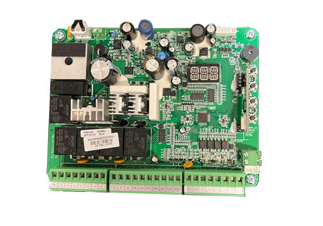
TMT 400LLS
View Wiring
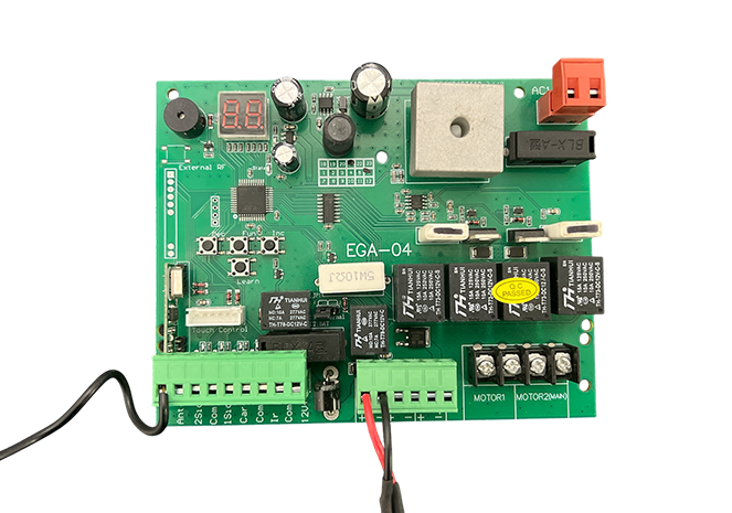
E8 - EGA-04 Board
View Wiring
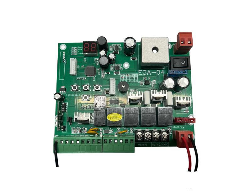
E8 - EGA-04 Board
with on/off switch
View Wiring
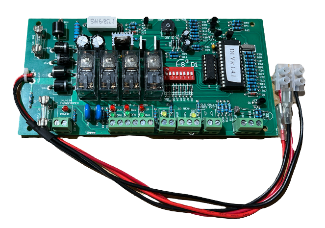
E8 - D1 Board
View Wiring